


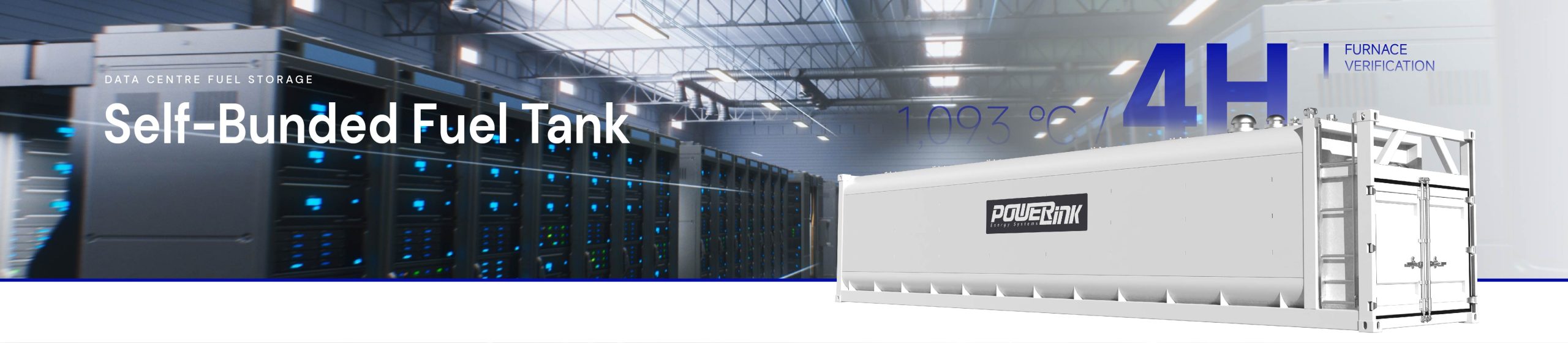
4 Hour

Diesel storage solutions for Data Centers & Industrial Projects
Self‑Bunded Fuel Tank for Diesel Generator
Diesel storage solution for data‑center & industrial projects, UL2085 4‑hour fire‑rated & AS‑standard compliant.


Technical Specifications
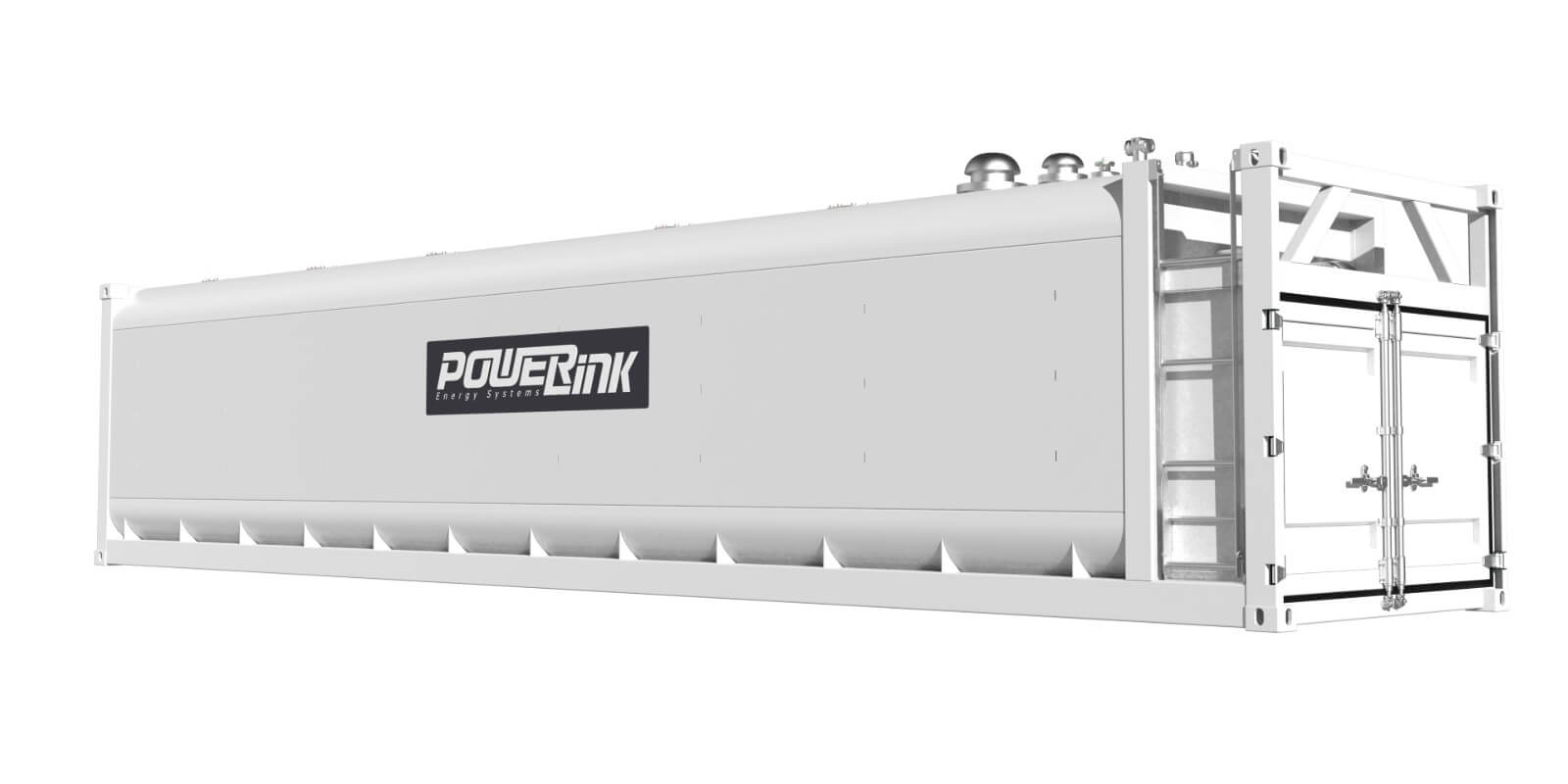
| Nominal / Safe Working Volume | 28,000L/26,600L(95%fil) |
| Containment Capacity | 110% Triple-barrier protection |
| Fire Rating | UL2085-4-Hour Fire Protected |
| Applicable Standards | AS1692 Cat5|AS1940-2017 |
| Interlayer Material | Light-weight fire-resistant concrete |
| Anti-corrosion Grade | C4/C5 environment, DFT >250um |
Five-Layer Composite Protection Structure
Multi-layer sequential defence against flame, heat-expansion and fluid leakage.
Primary Steel Tank
Heavy-gauge carbon steel for media containment.
Inner Ceramic Fibre Cushion
Thermal-expansion buffer & leakage flow guide.
Core Light-Weight Fire-Concrete
Primary thermal-insulation barrier.
Outer Thermal Fibre Mat
Suppress rapid moisture vaporisation under fire.
Outer Protective Shell
Mechanical impact & direct-flame resistance.
Safety Components

Overfill Valve

Anti‑Siphon Valve

Emergency Vent

Leak Detection

Top Containment Sump

Leak‑Proof Sleeve
FAQ
What special heat‑dissipation designs are available for the VR series for high‑temperature environments (e.g., the Middle East)? What interlayer thickness is required for fire‑resistance to pass the 4‑hour fire test? How does this differ from the basic 2‑hour UL 2085 requirement?
To satisfy the basic 2‑hour UL 2085 requirement, an insulation layer of 75‑100 mm is generally specified. To pass the 4‑hour fire‑resistance test at 2000 °F (1093 °C), high‑density blast‑resistant concrete typically requires an interlayer thickness of 150‑200 mm (6‑8 inches). The final outer envelope dimension shall be calculated by adding the double steel walls and interlayer thickness to the inner tank’s physical dimensions during design, so as to lock in installation space and access clearance in advance. For composite insulation solutions (insulation felt plus concrete), concrete thickness may be appropriately reduced.
Why must all openings be concentrated on the tank top? How shall top‑side connections be arranged?
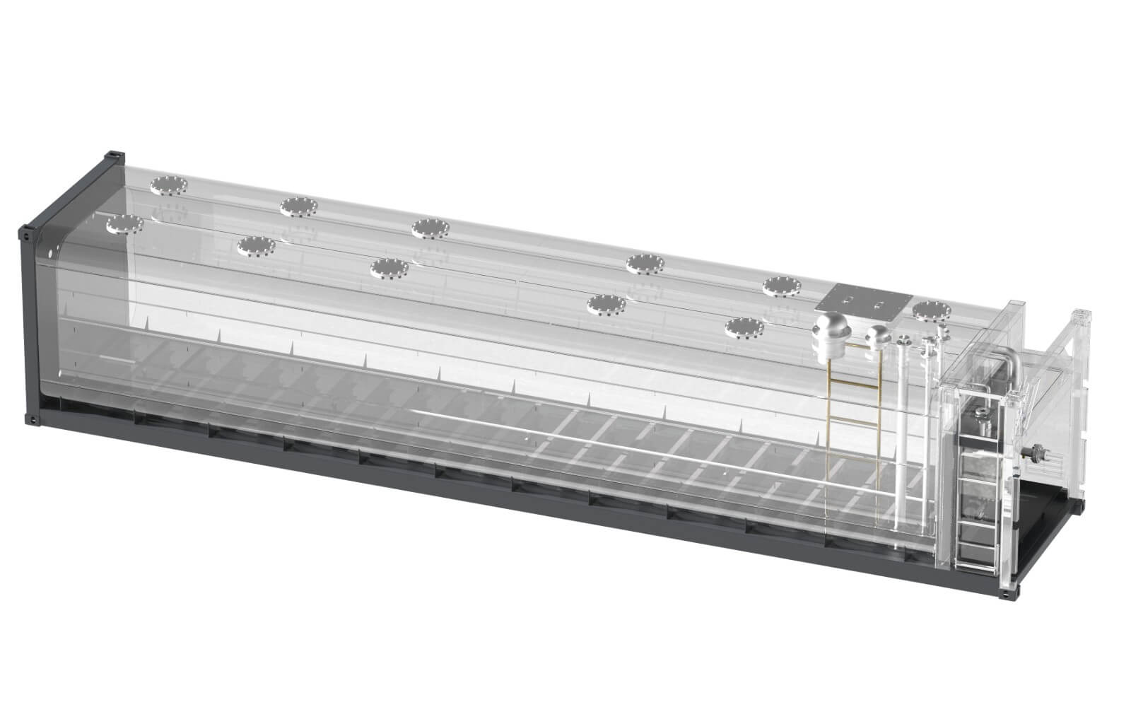
UL 2085 stipulates that all openings (fill, return, level‑measurement, venting, explosion relief, etc.) must be located above the maximum liquid‑level elevation. No openings are permitted on side walls or bottom plates to prevent medium leakage in case of pipe rupture. Standard top‑side connection layout for the 28,000‑L tank is shown below:
What mandatory requirements apply to the mix design of fire‑resistant concrete for the interlayer? Why cannot ordinary structural concrete be used?
When exposed to 1093 °C heating, ordinary structural concrete suffers explosive spalling caused by vaporization of internal free moisture. Large concrete sections peel off, resulting in loss of fire‑resistance performance. Mix‑design requirements:
- Polypropylene anti‑spalling short fibers — fibers melt under high temperature to form micropores, releasing vapor pressure and preventing concrete spalling.
- Aggregate selection — carbonate aggregates (limestone) or expanded shale / ceramsite lightweight aggregates are preferred, featuring low thermal conductivity and good high‑temperature stability.
- Strength requirement — 28‑day compressive strength shall meet design values (per calculation report), to satisfy UL 2085 vehicle‑impact and projectile‑penetration resistance tests.
How to select nominal size and set‑pressure for emergency pressure‑relief valves? Why is a separate relief port required for the interlayer?
- Primary inner‑tank emergency relief valve (V‑01): Minimum relief area under 4‑hour high‑temperature exposure shall be calculated using the wetted‑area heat‑absorption formula in UL 2085 appendix. For 28,000‑L capacity, a UL‑certified DN250 (10‑inch) relief valve or dual DN200 (8‑inch) relief valves are generally required. The valve is normally sealed by dead‑weight cover; it lifts automatically to vent high‑temperature oil‑gas at inner‑tank pressure of 17.2‑34.5 kPa (2.5‑5.0 psi). Opening pressure shall be lower than the inner tank’s maximum allowable working pressure.
- Interlayer emergency relief valve (V‑02): DN150 (6‑inch). It releases pressure generated by expansion of free moisture and trace oil‑gas inside concrete interlayer during fire events, preventing rupture of the outer steel shell.
- Normal breathing valve: Sizing for routine fill‑and‑draw ventilation per NFPA 30 / UL 142 (DN50, fitted with flame arrester).
Why are anti‑siphon valves and anti‑overflow valves mandatory items?
- Anti‑siphon valve (V‑03, DN50, UL‑certified) installed above supply‑outlet penetration: It automatically cuts off liquid column upon pump shutdown or pipe rupture, preventing complete siphon‑discharge of approx. 23.5 tons of diesel fuel from the 28,000‑L tank.
- Anti‑overflow valve (V‑04, DN80, mechanical shut‑off type, UL‑certified) fitted at fill port: It automatically closes fill flow at 95 % liquid level, preventing overflow from tanker / FTS delivery systems. Together with emergency relief valves, these items represent core components for fire‑safety and insurance compliance acceptance, and must bear UL 142 / UL 2085 nameplate stamping.
Valves and sensors are single‑wall metallic components. How is double‑wall leak containment (secondary containment) satisfied?
Globally accepted approach: “Single‑wall components housed within double‑wall containment enclosure”.
- Top containment sump: All single‑wall valves for supply, return, fill and sensing are centrally arranged. A fully welded metal containment sump is installed overhead. Its bottom plate is joined to outer shell steel plate; sump walls are constructed of heavy‑gauge steel. Leaks from failed gaskets or connections are collected inside the sump. A drain / bleed valve plus miniature leak‑detection probe (S‑04) are fitted at the sump low‑point; micro‑leaks trigger alarm and interlock‑shutdown of FTS pumps.
- Double‑end full‑welded penetration sleeves: Heavy‑wall sleeves are welded in‑situ prior to concrete pouring. Each sleeve is fully welded to outer shell at upper end and fully welded to inner tank at lower end, forming complete secondary‑containment boundaries. Process medium never contacts concrete.
- Level / leak‑detection sensors: Probes are enclosed within stainless‑steel monitoring wells / thermowells penetrating into tank interior to provide physical isolation.
- Piping connections outside containment sump adopt double‑wall flexible metal hoses.
- Pump assemblies are mounted inside leak‑proof drip tray integrated within upper section of control cabinet. Drip‑tray volume is sized for 110 % potential collected liquid, with leak‑detection sensor installed. Exception: Emergency relief valves are recognized single‑wall safety‑relief devices per codes and shall be exposed. Double‑wall enclosures would impair relief performance. Two points shall be clearly documented within certification submission packages: “All top‑mounted single‑wall valve components are enclosed within secondary‑containment‑compliant top containment sump; all concrete‑penetrating interfaces adopt double‑end full‑welded steel sleeves for isolation.”