


How to Size a Data Center Backup Generator for N+1 and 2N Redundancy
Data center backup generator sizing begins with three decisions: how much load the site has to carry, how much redundancy the tenants require, and which voltage level the distribution can accept. Capacity, switchgear, and cable all follow from those three answers, so settling them early keeps the specification from drifting later.
This guide follows the sequence PowerLink applies to hyperscale and colocation projects. It starts with the load list that every later figure depends on and ends with the checks worth running before the equipment list is issued. Details of the full equipment range are set out on the data center generator solutions.
What the Backup System Actually Has to Carry
The most common sizing error is measuring load against the IT nameplate alone, because a generator carries everything the utility would have carried once the UPS stops covering the gap. Two load families sit behind the switchgear, and a Tier III or Tier IV design has to back up both. IT load covers servers, storage, networking, and the equipment feeding them, while mechanical load covers the chillers, pumps, cooling towers, and air handlers that hold white space inside its thermal envelope.
Power usage effectiveness, or PUE, describes how much facility power it takes to deliver a single unit of IT power. Because that ratio moves with climate, cooling architecture, and rack density, it should be taken from your own metered data rather than from an industry average. Redundancy boundaries deserve the same care as the total, since a system sized to carry everything is not the same as one sized to survive a single module failure.
Starting From IT Load
IT load anchors the exercise, and every other figure descends from it, which is why the number is worth confirming twice before anything is ordered.
Server, Storage, and Network Load
Measured power is a more reliable starting point than nameplate ratings, since nameplate values describe the maximum a power supply can draw rather than what it draws in service. Metered data from a comparable facility makes a useful cross-check. Keeping the tally in kW lets figures from different voltage levels be added together. Separating critical blocks from non-critical ones shows what genuinely has to survive a utility outage.
Cooling and Mechanical Load
Chillers and air handlers dominate the mechanical block, and their motors draw a heavy inrush at start. That inrush, rather than the steady-state total, sets the transient requirement the generator has to ride through. Mechanical load also arrives in steps, because a chiller start behaves like a discrete jump instead of a gentle ramp.
Growth Margin
Few facilities reach their design load in the first year, since capacity fills over time and each hardware refresh tends to raise rack density. The growth margin added on top of today’s IT load therefore has to be carried into every downstream decision and kept visible in the load list. A figure that vanishes into a rounding step cannot be defended later.
Choosing Between N+1 and 2N
Where N+1 Fits
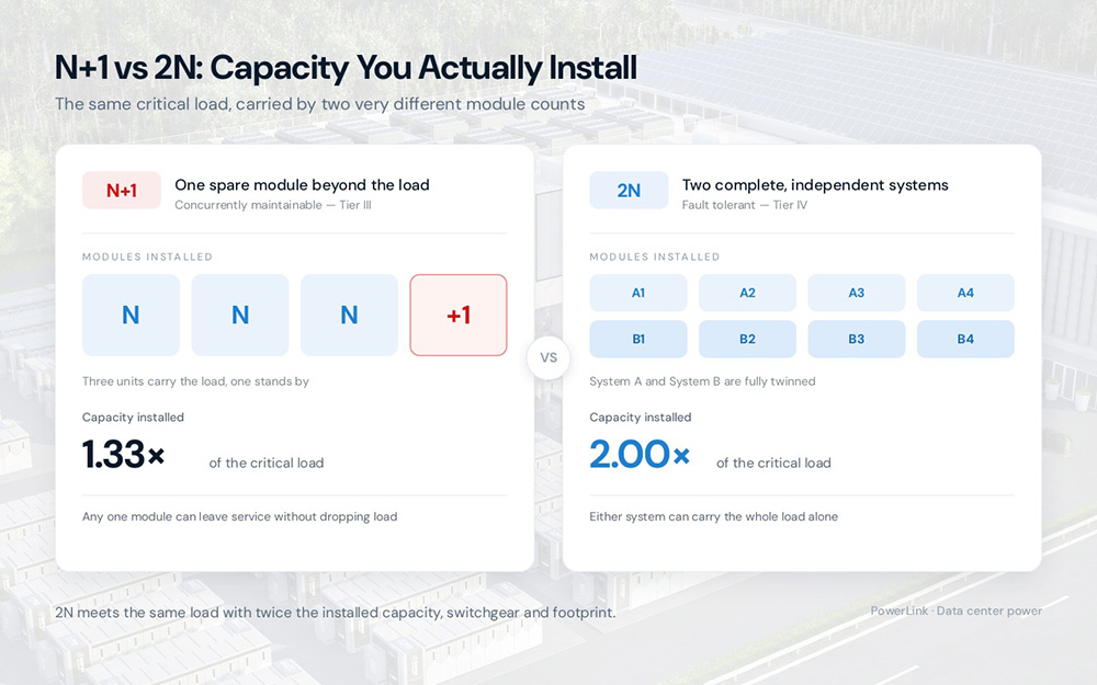
N+1 puts one module beyond what the load requires. An array that carries full load with a single unit on standby can then tolerate a failure or a maintenance outage without dropping load. It suits colocation halls with less demanding tier targets and sites built in stages. It also costs less than a mirrored system, because the spare is one module and not a complete second system.
Where 2N Fits
2N provides two complete systems, each able to carry the whole load, with every unit twinned on a separate bus. This is the usual answer for hyperscale AI halls and financial tenants that cannot accept a maintenance window, and the trade-off is that installed capacity and switchgear count roughly double.
How Generator Redundancy Relates to Tier III and Tier IV
Tier III is concurrently maintainable, meaning any component can leave service without dropping load, while Tier IV adds fault tolerance so that a failure coinciding with maintenance still does not interrupt the load. Generator redundancy is only part of that picture. An N+1 generator arrangement is a necessary but not sufficient condition for Tier III, because the tier also requires multiple independent distribution paths rather than a single path with spare generation attached to it. Tier IV does not settle on one arrangement either, since 2N and 2 (N+1) are both accepted routes to it. PowerLink gensets support multi-unit paralleling in both arrangements, and the wider range sits under data center power solutions.
Both options compare as follows.
| Item | N+1 | 2N |
| Spare strategy | One extra module beyond load | Two full systems, each fully rated |
| Typical use | Colocation halls, staged builds | Hyperscale AI halls, financial tenants |
| Tier relationship | Necessary but not sufficient for Tier III | One accepted Tier IV arrangement alongside 2 (N+1) |
Which one fits depends on how much downtime the tenants can absorb and how much they are prepared to pay to avoid it.
Low Voltage or Medium Voltage
Voltage level follows from capacity and distance rather than preference, and the choice changes cable, switchgear, and transformer scope at the same time.
When 400 V and 480 V Work
Low voltage gensets connect straight into the site distribution board, so no transformer is needed between the generator terminals and the load. PowerLink 400 V/480 V gensets run from 1600 kW (2000 kVA) to 3000 kW (3750 kVA) on 50 Hz / 400 V / CE builds. The 60 Hz / 480 V / UL / EPA builds cover 1600 kW (2000 kVA) and 1800 kW (2250 kVA). Low voltage makes sense when the generator stands close to the load and the paralleled total stays inside the interrupting rating of the switchgear it feeds.
When 4.16 kV to 13.8 kV Pays Off
Medium voltage 4.16 kV to 13.8 kV gensets output 4.16 kV, 10.5 kV, 11 kV, or 13.8 kV. At that level a much smaller conductor carries the same power across a long run from the generator yard. Ratings span 2000 to 3000 kW on 50 Hz / 10.5 to 11 kV builds, and 1600 to 3600 kW on 60 Hz / 4.16 to 13.8 kV builds. A PLC-500 controller parallels units for N+1 or 2N schemes.
Cable Cost and Line Loss
Current drives cable cost, and voltage sets current for a given power, so a low voltage installation means heavy conductors and resistive losses that climb with load. Medium voltage cuts both line loss and cable investment across a large site, which offsets part of the transformer and switchgear it adds.
| Item | Low voltage (400 V / 480 V) | Medium voltage (4.16 kV to 13.8 kV) |
| Factory compliance | CE for 50 Hz; UL and EPA for 60 Hz | Built to local switchgear requirements |
| Rating span | 1600 to 3000 kW | 1600 to 3600 kW |
| Best fit | Generator close to the load | Long runs and large paralleled blocks |
The right answer usually follows the site layout, because a compact hall with the plant room next door behaves differently from a campus with generators at the fence line.
Matching the Genset to a GPU-Heavy Load Profile
Harmonics From Nonlinear UPS Loads
The GPU era changed how data center backup generators are sized, because demand now steps higher and faster than traditional colocation design assumed. Modern UPS units and switch-mode supplies are nonlinear loads. They draw current in short pulses and return the distortion to the generator as harmonics, which raises heating in the alternator and can destabilize voltage regulation. Harmonic suppression therefore has to be designed in, and PowerLink applies it so the generator does not push harmonic pollution back onto the grid.
Three-Second Recovery and Load Steps
GPU racks can swing from idle to full draw in a single step, which makes recovery time the metric worth watching. PowerLink AIDC units restore voltage and frequency to steady state within 3 seconds under severe load steps, a performance the company rates as Tier III grade. The engines used in the Australian project tell a related story, since Perkins units reach 8-second start and 15-second full-load acceptance.
Full Rating at 50 °C
Ambient temperature eats into generator capacity, and many manufacturers derate above a reference temperature. PowerLink AIDC gensets deliver full rated power at 50 °C ambient without derating, from 2000 kW upward into MW-scale paralleled clusters.
Whether Storage Should Bridge the Gap
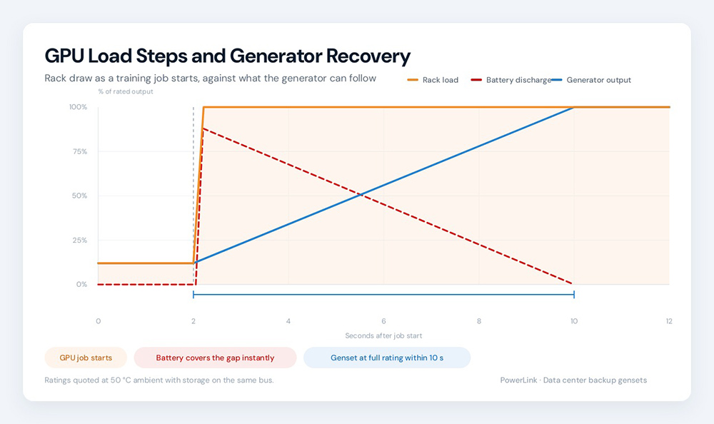
A generator does not energize instantly, and the 0 to 15 second figure quoted in most specifications describes the diesel engine crank-to-start time alone. A complete transfer to the load also involves automatic transfer switch operation, synchronizing and paralleling where several units share a bus, and a retry when a first start attempt does not catch. The UPS bridging reserve a site actually needs therefore has to be sized above the engine start time rather than set equal to it, and the margin grows with the number of units in the paralleled block. Storage carries the critical load through the delay and hands it back once the generator is online.
Both PowerLink storage lines are described on the data center hybrid system. The PES series is the mobile option, with 30 to 500 kWe of output, 62 to 1040 kWh of battery, and inputs for both PV and diesel generation. Unit ratings run from the PES100S at 100 kVA/kW with 125 kWh and 60 kWp up to the PES400L at 400 kVA/kW with 466 kWh. The PES200S, PES200L, PES300S, and PES400S sit in between. These units operate from −20 °C to 55 °C on lithium iron phosphate cells and accept overloads of 140%, 210%, and 374% for 10 seconds.
The PHE series is the liquid-cooled option, offering 125 to 500 kWe of output and 237 to 1040 kWh of battery at a 1C charge and discharge rate. It integrates diesel generation, intelligent EMS, and fire suppression, and complies with IEC, UL, and UN 38.3. Storage also earns its place on the utility bill, because peak shaving lets the battery cover excess load and avoid penalties. PowerLink publishes a figure of about 90% reduction in temporary diesel runtime, which is a company claim and not an independent study. Outdoor containerized deployment is part of the appeal, since it leaves indoor white space free for revenue-generating racks.
What a 60 MW Deployment Looks Like in Practice
The 60 MW AIDC project in Australia shows how those decisions land in hardware. Each unit delivers 2000 kW of continuous power at 2500 kVA, and the site runs 30 units for 60 MW of installed capacity across roughly 500 ㎡. Double-layer offset stacking reaches a system power density of 115.38 kW per ㎡, and every unit sustains full load across 24 hours of continuous running.
The upper cabin is a 40-foot high-cube container holding a Perkins engine, a Leroy-Somer generator, and silencing ducts. The integrated base beneath it carries more than 10,000 L of fuel storage, plus a day tank of more than 2,000 L. Redundant starting arrives as 1+1 independent start circuits, which gives a start success rate above 99.99%. Site conditions range from −40 °C with full-chain heat tracing to altitude compensation above 3000 m. The build is HVO biofuel compatible and can be specified with an optional EPA Tier 2 configuration.
Published ratings for the series appear below.
| Series | kW (kVA) ratings | Frequency / voltage | Noise (1 m, 75% load) | Fuel tank |
| Low voltage, 50 Hz | 1600 (2000), 1800 (2250), 2000 (2500), 2400 (3000), 2700 (3375), 3000 (3750) | 50 Hz / 400 V, CE | 79 / 85 dBA by rating | 2400 L |
| Low voltage, 60 Hz | 1600 (2000), 1800 (2250) | 60 Hz / 480 V, UL, EPA | 79 dBA | 2400 L |
| Medium voltage, 50 Hz | 2000, 2400, 2500, 2700, 3000 kW | 50 Hz / 10.5 to 11 kV | 85 dBA at 2400 kW and above | 2400 L |
| Medium voltage, 60 Hz | 1600, 1800, 3200, 3600 kW | 60 Hz / 4.16 to 13.8 kV | 79 dBA at 1600/1800 kW | 2400 L |
What to Lock Down Before You Issue the Specification
Four critical metrics dictate your entire specification. Locking these down early prevents expensive scope changes, as any late adjustment ripples directly through your capacity limits, switchgear sizing, and cable selection:
- The carefully measured IT load
- The projected growth margin
- The targeted redundancy level
- The operating system voltage
Before releasing the specification to suppliers, two operational checks matter far more than basic datasheet figures. You must verify the transient response against the absolute largest single load step, not just the steady state average. Furthermore, you must confirm the ambient thermal rating against the hottest possible day your specific site will ever see. Once these boundaries are locked in, the remaining sizing arithmetic becomes perfectly straightforward.
Finalizing Your Power Strategy
Securing continuous power for a modern data center requires far more than simply matching a generator rating to a theoretical facility footprint. Locking down your true metered load, planning a realistic growth margin, and leveraging intelligent battery storage to safely bridge any start delays will transform a basic specification into a truly resilient power strategy. When you build your entire system around how the facility actually behaves under sudden stress, your critical load remains fully operational long after the utility grid goes dark.
Eliminate the guesswork from your next deployment by having our engineering team review your specific load profile. Send us your measured IT load, your targeted redundancy level, and the absolute maximum ambient temperature for your site. Contact PowerLink and we will help you size and specify a backup architecture guaranteed to keep your facility operational when the utility grid goes dark.